
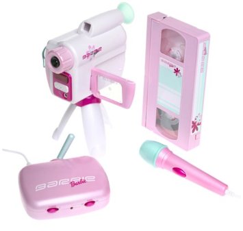
The original video camera and receiver. It also apparently came with a microphone and VHS tape. (Stock photo)
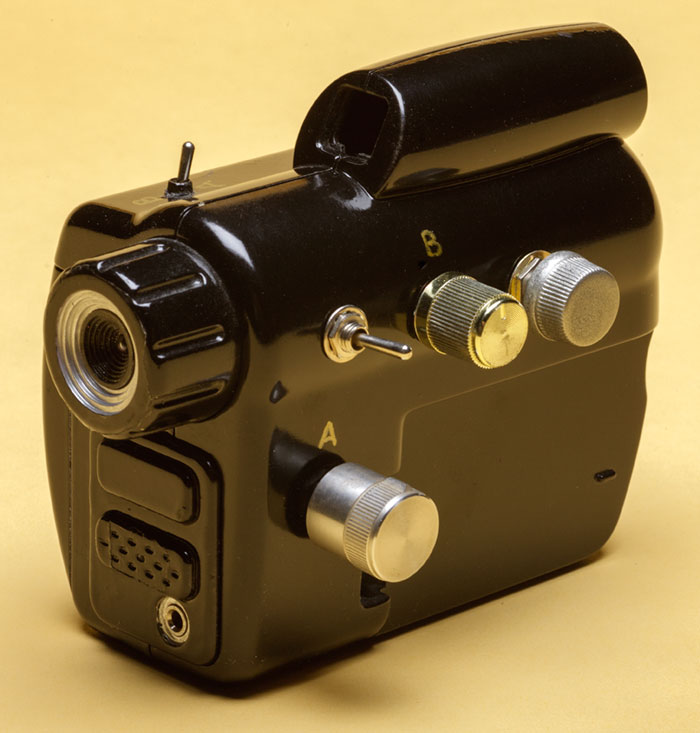
Modified camera. Removed the fake fold-out LCD screen.
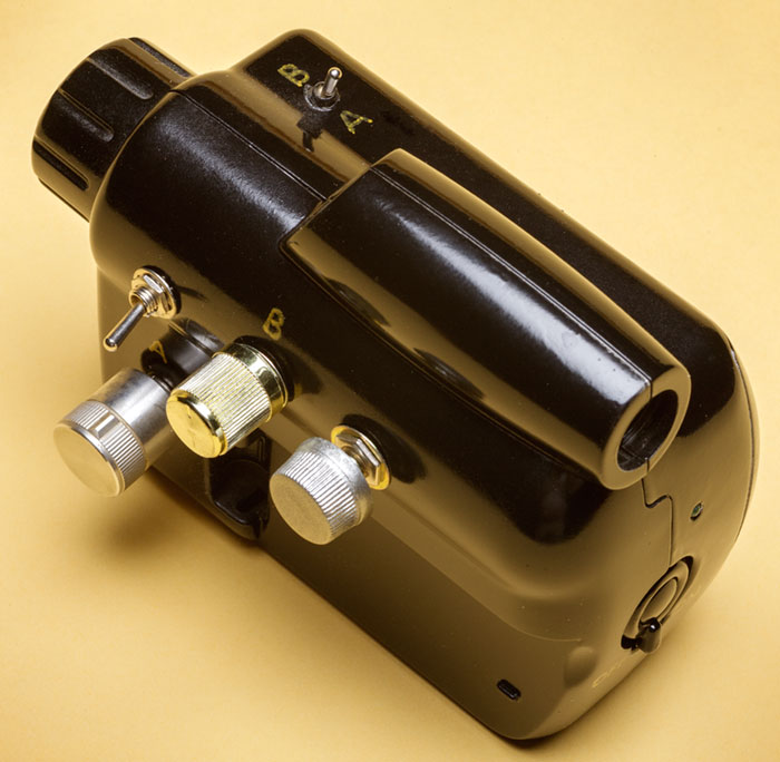
The 'A/B' switch on top chooses between the two available transmit channels. The A & B knobs on the side tune or de-tune the channels slightly for noisey effects.
The Chip datasheets:
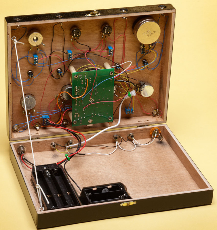
Inside finished box. New battery holders fitted, so unit can be run in the field on battery power.
|
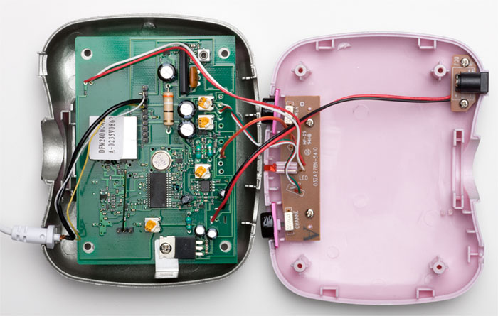
Inside the receiver case.
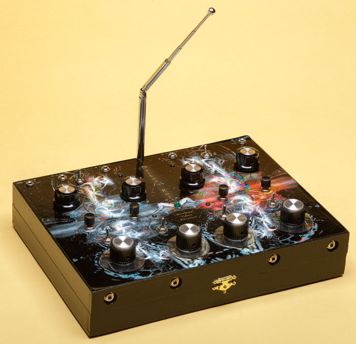
Re-housed receiver with glitch controls. Antenna is detachable. There are 1/8" jacks at the top for external photocell control of glitches, and 1/8" jacks on the front for external control of the 4 switches.
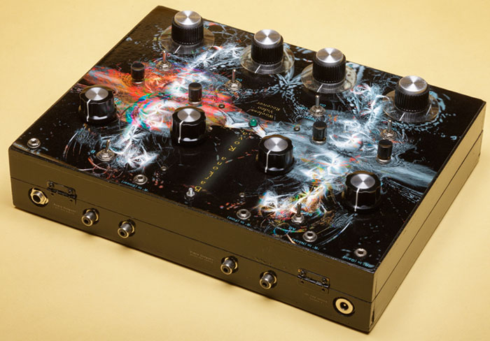
Back view of the receiver, antenna removed. Video and audio outputs are here, as well as an input for the AC adapter (unit can be switched between battery or AC power).
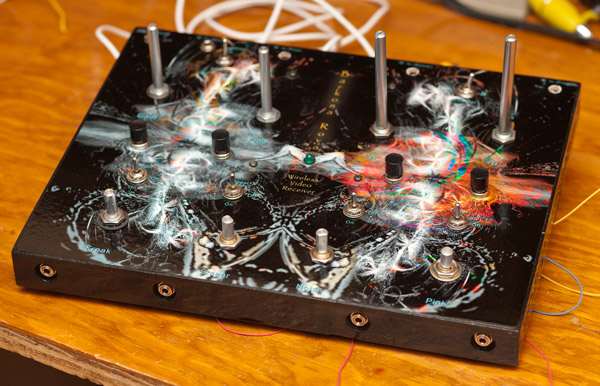
Re-housing the receiver. Work in progress.
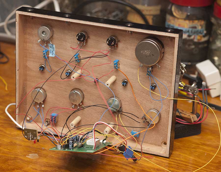
Underside of the receiver lid. Wooden dowels were placed as standoffs to attach the circuit board.
| ||||||||
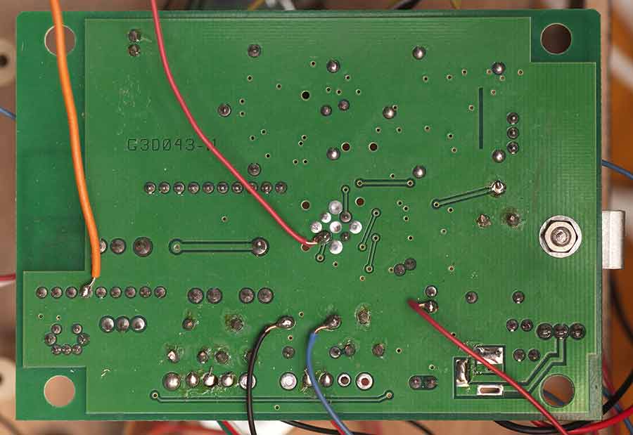
Underside of the receiver circuit board showing wire attachment points for bends.
|
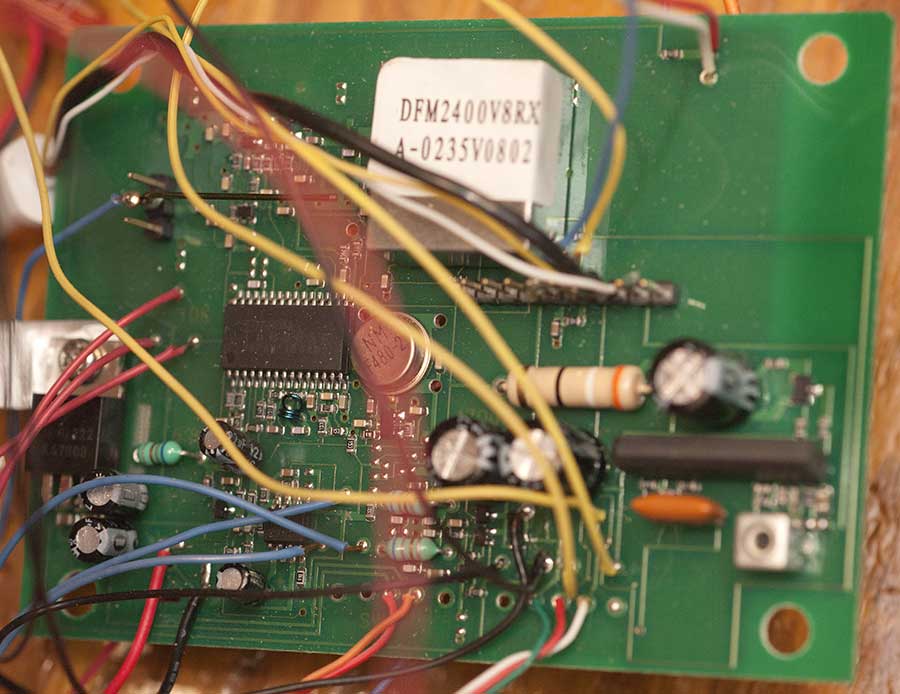
Component side of circuit board from receiver, showing attached wires for bends.
|
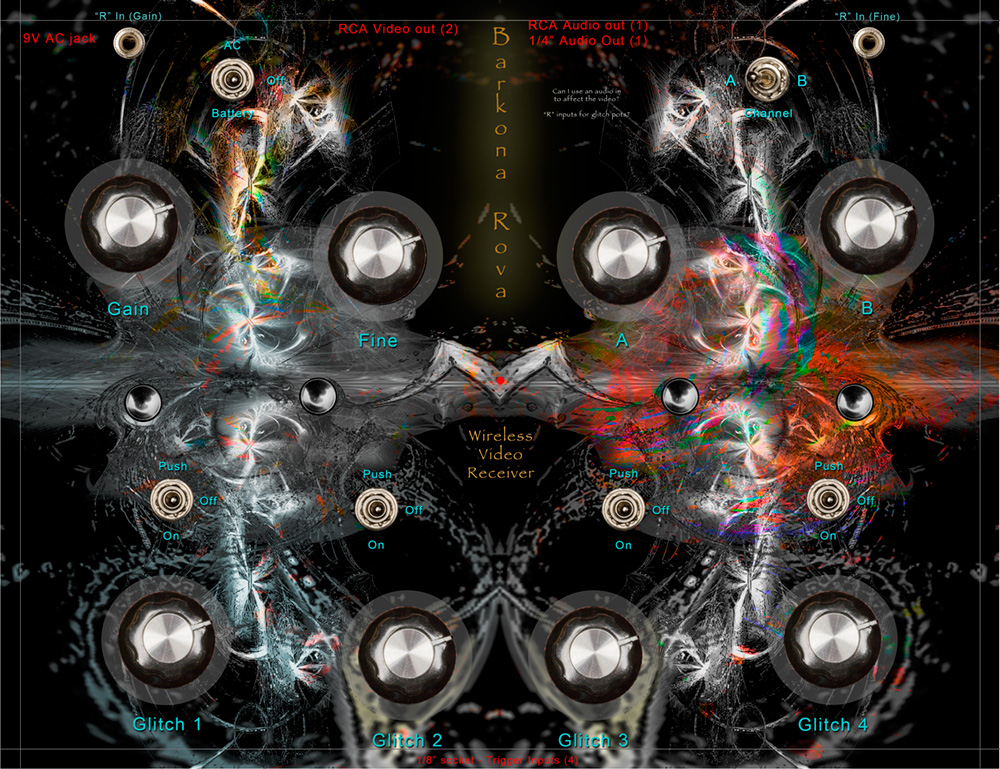
Working on the box art.
